
Updated September 28, 2026.
Installing a 6.7 Cummins intake horn is not one identical job across every 2007.5–2024 Ram. Pickup and Chassis Cab layouts, EGR connections, grid-heater hardware, sensors, fuel-line routing, brackets, and included parts can change by model year and selected kit. Identify the truck and installation path before removing the first component.
Key takeaway: A clean, stock pickup can often require roughly 3–5 hours for an experienced installer, while a grid-heater change, fuel-line work, heavy carbon buildup, damaged hardware, previous modifications, or a crowded Chassis Cab layout can extend the job to roughly 5–8 hours or more. The 18–20 ft-lb value applies only to intake-manifold fasteners identified in the applicable SPELAB procedure; it is not a universal torque specification for every 2007.5–2024 fastener.
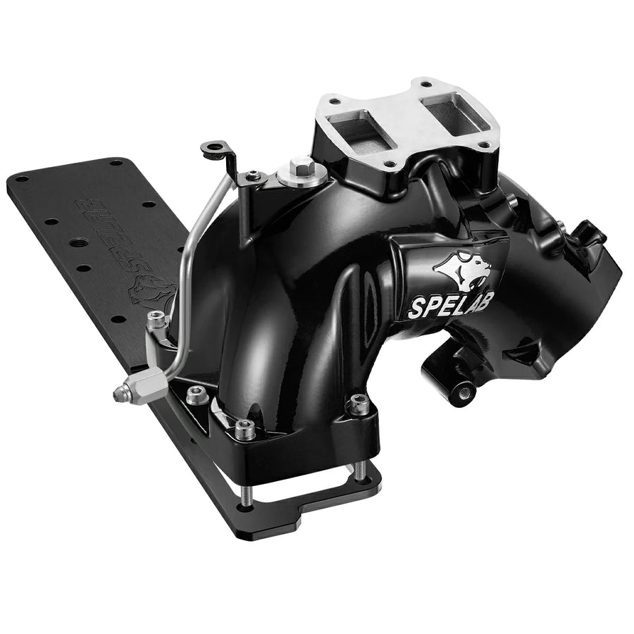
6.7 Cummins Intake Horn Installation at a Glance
| Planning Item | Practical Guidance |
|---|---|
| Typical time | Roughly 3–5 hours for an experienced installer on a clean, stock pickup; often 5–8 hours or more when additional heater, fuel-line, carbon-cleaning, damaged-hardware, or Chassis Cab work is required |
| Difficulty | Moderate to advanced DIY, depending on whether fuel, EGR, heater, or configuration-specific components must be disturbed |
| Main engine risk | A bolt, washer, gasket fragment, abrasive particle, or shop-towel fiber entering an uncovered intake port can cause severe internal engine damage |
| Main personal-safety risk | High-pressure diesel fuel can penetrate skin; never use a hand or finger to search for a fuel leak |
| Torque boundary | Use 18–20 ft-lb, approximately 24–27 N·m, only for the intake-manifold fasteners identified by the applicable SPELAB procedure; verify every other fastener separately |
| Final verification | Check for fuel, boost, air, electrical, and heater-system problems before applying load, then scan for stored or pending fault codes |
Identify the Exact Installation Path Before Starting
“It is a 6.7 Cummins” is not enough fitment information. Record the model year, VIN, Pickup or Chassis Cab body, single- or dual-alternator arrangement where relevant, EGR status, grid-heater strategy, existing intake modifications, product handle, and selected variant before comparing the truck with the instructions.
| Truck or Configuration | Verify Before Disassembly | Installation Direction |
|---|---|---|
| 2007.5–2012 Pickup | Exact intake-horn design, EGR layout, grid heater, sensors, fuel line, throttle connection, gaskets, and included hardware | Use the instructions for the selected 2007.5–2012 variant; do not copy later-model connector or fuel-line steps |
| 2013–2018 Pickup | OLD fabricated or NEW cast design, EGR connection, fuel-rail support, fuel-line parts, sensor locations, grid-heater plate, and four-port or two-port layout | Follow the exact kit instructions; use the 2018 walkthrough only when its truck and configuration match |
| 2019–2024 Pickup | 2019+ manifold variant, fuel and sensor connections, EGR and heater configuration, wiring, brackets, and included plugs | Use the later-model instructions or installation video supplied for the selected variant |
| Ram 3500/4500/5500 Chassis Cab | Chassis Cab-specific kit, tube layout, dual-alternator clearance where applicable, heater element, wiring, brackets, and body-specific access | Do not substitute Pickup instructions or assume a Pickup manifold bundle includes the required Chassis Cab parts |
| Previously modified truck | Aftermarket turbo, charge pipe, intake, EGR changes, heater changes, calibration, added sensors, non-stock fuel routing, and prior wiring repairs | Resolve fitment and calibration conflicts before installation rather than modifying the new part during assembly |
Use the 6.7 Cummins intake-horn compatibility guide to select the correct year and configuration before returning to this installation checklist.
Tools and Materials
- Metric sockets, wrenches, extensions, and any Torx or line tools specified for the exact truck
- A calibrated torque wrench covering the required range without operating at the extreme end of its scale
- Plastic scraper or other non-marring gasket-removal tool
- Lint-free wipes, clean intake-port covers, inspection light, mirror, and telescoping magnet
- Vacuum suitable for controlled debris removal around protected ports
- Sensor-safe cleaner for compatible MAP or temperature sensors
- Clean, purpose-made caps or plugs for any fuel connection the applicable procedure requires opening
- New gaskets, O-rings, seals, fittings, plugs, brackets, and fasteners specified for the selected kit
- Approved thread sealant or threadlocker only where the kit instructions call for it
- OBD scan tool capable of reading stored, pending, and manufacturer-relevant fault information
Do not assume that commonly mentioned 6 mm, 10 mm, or 12 mm tools cover every year or configuration. Lay out the exact kit, compare it with the parts list, and obtain any missing line tool, seal, or one-time-use component before the truck is disabled.
Critical Safety Checks
Disconnect both batteries: Allow the engine to cool, switch the ignition off, and disconnect both negative battery terminals before working around intake-heater wiring, sensors, fuel components, or exposed conductors.
Protect every intake opening: Cover each open intake passage immediately after the component is removed. Use compressed air only before the ports are opened; once an intake passage is exposed, control debris with protected openings and a vacuum instead of blowing contamination around the engine.
Treat common-rail fuel as a medical hazard: High-pressure diesel fuel can penetrate skin and cause a high-pressure injection injury. Never loosen a pressurized connection, never search for a leak with a hand, and seek immediate emergency treatment if fuel penetrates the skin. If the exact procedure requires opening a fuel connection, keep the area surgically clean, cap both sides immediately, and follow the specified replacement and priming requirements.
Confirm emissions compliance before changing the EGR system: An intake-horn installation does not automatically require EGR removal. For U.S. road vehicles, the EPA states that the Clean Air Act prohibits modifications that bypass, defeat, or render required emissions controls inoperative. Confirm the legal configuration before purchasing or installing related parts.
Universal Installation Workflow
The following workflow covers checks that are broadly useful across the product family. Connector locations, fuel-line procedures, EGR hardware, heater components, bracket arrangements, and torque values must still come from the exact kit and model-year instructions.
1. Verify the Kit and Document the Truck
Compare the selected variant, product label, included-parts list, gaskets, O-rings, fittings, plugs, brackets, fuel-related components, heater parts, and instructions with the truck before disassembly. Photograph connector routing, hose positions, clamp orientation, grounds, brackets, and any existing modifications.
2. Park Safely, Cool the Engine, and Disconnect Both Batteries
Park on a level surface, apply the parking brake, allow hot intake and exhaust components to cool, and disconnect both negative battery terminals. Isolate the cable ends so they cannot spring back onto the terminals.
3. Clean the Work Area Before Opening the Intake
Remove loose dust, grit, leaves, oil residue, and carbon from the top of the engine before any intake passage is exposed. Cleaning the area first reduces the chance that debris will fall into a port while the installer reaches for a tool or moves a harness.
4. Remove Only the Components Required by the Selected Procedure
Remove the intake tube, charge-air connection, brackets, sensors, hoses, harness retainers, and configuration-specific components identified by the instructions. Label similar connectors and retainers. Do not bend, loosen, or reposition a high-pressure fuel line merely to gain clearance unless the exact service procedure requires it.
Owners working on a matching truck can use the 2018 Ram 2500 installation walkthrough for a more specific example; other years should not copy its connector, bracket, fuel, or heater steps without verification.
5. Remove the Factory Horn and Cover the Ports
Loosen the identified fasteners gradually, support the component as it separates, and account for every bolt, washer, spacer, gasket, and clip. Cover each exposed intake opening immediately. Count removed hardware before cleaning or unpacking the replacement part.
6. Clean and Inspect the Sealing Surfaces
Use a plastic scraper or non-marring method to remove gasket residue without gouging the mating surface. Keep ports covered and vacuum loose debris. Inspect for corrosion, raised burrs, damaged threads, warped flanges, old sealant, and foreign material; extra torque cannot safely correct a shifted gasket or damaged sealing surface.
7. Install the Correct Gaskets and Position the New Manifold
Place every square gasket, round gasket, O-ring, spacer, or plate in the position specified for the selected configuration. Do not add RTV unless the instructions require it. Lower the manifold into position without disturbing the seals, then start every mounting bolt by hand to confirm alignment and prevent cross-threading.
8. Tighten Only to the Verified Specification
Snug the identified manifold bolts evenly and follow the sequence supplied for the kit. The applicable SPELAB procedure identifies 18–20 ft-lb, approximately 24–27 N·m, for specific intake-manifold fasteners; that value must not be transferred to sensors, NPT fittings, fuel connections, heater studs, brackets, clamps, or unidentified model-year hardware.
9. Install Heater, Sensors, Plugs, and Fittings
Install the retained factory heater, delete plate, or replacement heating component only as specified for the chosen configuration. Inspect compatible MAP and intake-temperature sensors and clean them with a sensor-safe method when contamination is present. Seal unused NPT ports with the approved product and stop when the tapered fitting seals; forcing another turn can crack or distort an aluminum port.
10. Reconnect Fuel, Air, Electrical, and Support Components
Reconnect every hose, clamp, bracket, harness retainer, sensor, ground, intake tube, and procedure-required fuel component. Route wiring and lines away from sharp edges, exhaust heat, belts, pulleys, and rubbing points. Replace any one-time-use seal or fuel component required by the applicable service information.
11. Perform the Pre-Start Inspection
Remove every intake-port cover and account for all tools and hardware. Confirm that clamps sit correctly, unused ports are sealed, wiring is supported, fuel connections are clean and complete, batteries are reconnected, and no rag, cap, plug, or fastener remains in the intake path.
12. Start, Inspect, Scan, and Load the Truck Gradually
Follow the required priming and first-start procedure when a fuel connection was opened. Stop if cranking becomes excessive or if fuel, smoke, abnormal noise, or a warning appears. After the engine starts, inspect visually for leaks without touching suspected high-pressure fuel areas, then scan for stored and pending codes. Begin the road check at light load and increase load only after idle operation, sensor data, and connections appear normal.
Torque Reference Without a False Universal Specification
| Fastener or Connection | Guidance | Main Risk |
|---|---|---|
| Intake-manifold fasteners identified in the applicable SPELAB procedure | 18–20 ft-lb, approximately 24–27 N·m, tightened gradually in the specified pattern | Applying the value to the wrong fastener or damaged thread |
| Grid-heater plate hardware | Use about 18 ft-lb only when the exact selected kit explicitly specifies that value | Distorting the plate, damaging threads, or creating an electrical-clearance problem |
| 1/8-inch NPT plug or fitting | No universal torque is provided here; use the specified sealant and installation method for the fitting and port material | Cracking the port, splitting the casting, or contaminating a sensor |
| Sensor, bracket, clamp, fuel fitting, or electrical stud | Use the exact component and model-year specification | Broken sensor body, stripped thread, fuel leak, poor electrical connection, or clamp failure |
Do not blanket-retorque every fastener after the first drive. Reinspect for leakage, movement, rubbing, loose clamps, unsupported wiring, or disturbed connectors, and perform a torque recheck only when the kit instructions specify the fastener, engine condition, sequence, and interval.
Retain, Delete, or Replace the Grid Heater?
A factory heater, delete plate, and replacement heating element are different configurations. A manifold-only purchase does not automatically remove the original grid-heater hardware, and a delete plate does not provide cold-start heat unless the selected system includes a compatible heating strategy.
Cold-start planning should use the lowest manifold-air temperature the truck regularly experiences. As one model-year example, the 2024 Ram owner information states that the intake-air heater can become active below about 66°F (19°C), while temperatures below 0°F (−18°C) require additional cold-start consideration. Exact control logic and procedures can vary by model year, so “the truck started once above freezing” is not enough evidence to remove the heater from a daily-driven work truck.
Battery condition, cranking speed, compression, fuel quality, calibration, altitude, wind exposure, block-heater use, heater output, and post-heat operation can all change cold-start behavior. Review the 6.7 Cummins grid-heater decision guide before selecting the installation path.
[[product-recommend:2]]Common Problems After Installation
| Symptom | Possible Cause | First Useful Check |
|---|---|---|
| Check-engine light | Unplugged sensor, bent terminal, open heater circuit, configuration change, pinched harness, or air leak | Save codes and freeze-frame data, then inspect every connector and circuit touched during installation |
| Hiss or whoosh under load | Shifted gasket, loose charge-air clamp, unsealed port, damaged coupler, or pipe misalignment | Inspect for an oil or soot track and perform a regulated charge-air leak test |
| Hard start or extended cranking | Fuel connection disturbed, battery terminal loose, heater fault, sensor unplugged, or incorrect priming | Stop repeated cranking and verify the affected fuel, battery, heater, and sensor systems |
| Rough idle or poor throttle response | MAP/IAT data error, shared 5-volt-reference fault, boost leak, gasket problem, or unrelated engine fault | Compare scan data with expected key-on and cold-soak readings before replacing a sensor |
| Soot trail near an EGR connection | Misaligned connection, damaged gasket, loose clamp, or incompatible configuration | Inspect the exact joint and gasket rather than tightening unrelated manifold bolts |
| Rattle, rub, or vibration | Loose bracket, unsupported wiring, line contact, pipe contact, or missing retainer | Inspect clearances at idle and after the engine moves under light load |
The post-install fault-code guide provides the next diagnostic step when a warning or drivability problem remains after the visual inspection.
What Should Change After Installation?
A compatible intake horn can reduce a local airflow restriction, but a stock truck may show little measurable or seat-of-the-pants change. Towing response and high-load airflow depend on turbocharger output, charge-air leaks, fueling, calibration, engine condition, trailer weight, road grade, elevation, ambient temperature, and the rest of the intake and exhaust path.
An intake horn does not repair a weak turbo actuator, charge-air leak, contaminated sensor, fuel-pressure fault, restricted DPF, EGR fault, injector problem, or incorrect calibration. Read the analysis of whether a 6.7 Cummins intake horn helps before treating the installation as a guaranteed horsepower, MPG, EGT, or towing upgrade.
6.7 Cummins Intake Horn Installation FAQ
How long does a 6.7 Cummins intake-horn installation take?
An experienced installer can often complete a compatible intake-horn installation on a clean, stock pickup in roughly 3–5 hours. Grid-heater work, fuel-line changes, heavy carbon deposits, damaged fasteners, previous modifications, missing parts, or a Chassis Cab layout can extend the job to roughly 5–8 hours or more.
Does one installation procedure cover every 2007.5–2024 Ram 6.7 Cummins?
No. 2007.5–2012, 2013–2018, and 2019–2024 pickups can use different manifold variants, EGR connections, grid-heater components, sensors, fuel-line arrangements, brackets, and wiring. Ram 3500/4500/5500 Chassis Cab applications can also require dedicated tube and clearance configurations.
Which 6.7 Cummins intake-manifold fasteners use 18–20 ft-lbs?
The 18–20 ft-lb range, approximately 24–27 N·m, applies only to intake-manifold fasteners identified in the applicable SPELAB installation procedure. Sensors, tapered NPT fittings, fuel connections, heater studs, brackets, clamps, and other model-year configurations require their own verified specifications.
Can the factory grid heater be retained with an upgraded intake horn?
The factory heater can be retained only when the selected manifold variant and installation hardware support that configuration. Other variants use a delete plate or replacement heating element, so the heater strategy must be confirmed by exact SKU before disassembly.
What should cold-climate owners verify before changing the grid heater?
Cold-climate owners should verify the truck's lowest regular manifold-air temperature, battery and cranking condition, block-heater availability, replacement-heater output, circuit monitoring, calibration, and expected post-heat operation. Some factory systems use intake heat above 32°F, so freezing temperature alone is not a sufficient decision boundary.
What commonly causes a check-engine light after intake-horn installation?
Common causes include an unplugged MAP or temperature sensor, bent connector terminal, pinched harness, open heater circuit, unsealed NPT port, shifted gasket, boost leak, loose ground, or an EGR or heater configuration that does not match the truck's calibration. Save the codes and freeze-frame data before clearing them.
How should 1/8-inch NPT plugs and fittings be installed?
A 1/8-inch NPT fitting uses tapered threads and should be installed with the sealant and method approved for the fitting, sensor, and aluminum port. Keep sealant out of the air stream and sensor tip, and do not force another turn after the joint seals because excessive torque can crack or distort the port.
What must be checked before the first start?
Before the first start, remove every intake-port cover, account for tools and hardware, verify all gaskets and plugs, seat each connector and clamp, support wiring and lines, confirm procedure-required fuel connections, reconnect both batteries, and follow the specified priming procedure if the fuel system was opened.
Sources and Technical Boundaries
- Fitment and configurations: Current SPELAB product variants and the linked model-year compatibility guide, reviewed September 28, 2026.
- Torque: The 18–20 ft-lb range comes from the applicable SPELAB procedure for its identified intake-manifold fasteners and is not presented as a universal Ram specification.
- Installation time: The 3–5-hour and 5–8-hour ranges are conservative planning estimates, not factory flat-rate allowances or guaranteed completion times.
- Cold-start operation: The 66°F (19°C) and 0°F (−18°C) examples come from 2024 Ram owner information; exact system behavior and procedures can vary by model year.
- Emissions: Road-use legality depends on the installed configuration and applicable federal, state, local, inspection, and warranty requirements.
Final Installation Checklist
- Exact model year, body style, product variant, EGR status, and heater strategy confirmed
- Kit parts, seals, instructions, tools, and any one-time-use components verified before disassembly
- Both batteries disconnected and every open intake port protected during the work
- Fuel connections handled only when required by the exact procedure and checked without hand contact
- Each fastener tightened to its own verified specification rather than one universal value
- All sensors, grounds, wiring retainers, hoses, clamps, plugs, and brackets accounted for
- First start, visual leak inspection, scan check, light-load road test, and post-drive inspection completed


4 comments
It looks like no one is monitoring this question thread.
I need to make sure the grid heater delete / intake manifold includes the new heating element or if I can buy the element separately for you all.
I don’t find it on your site anywhere.
Please let us know something.
Does the intake come with the heating element
Good day,
I’m looking at your replacement intake for 2018 6.7 Cummins. I’d like to keep the intake heating capability with a screw in intake element. However, I don’t see any element on your site. Is that available through you, or do I need to search elsewhere? Can you tell me what part would fit?
After installing my intake manifold my truck is shifting awfully what do I need to check or possibly did wrong?
Before installation shifted smoothly. And just got it efi live tuned before the intake horn installation.